PMO Robotics / Invention 18
PMO Exergy Core
A real-time exergy intelligence and recovery platform concept that measures where useful-work potential exists, estimates how much is recoverable, and routes recovery only when measured net value exceeds parasitic cost.
Scientific boundary: Exergy Core does not create energy, destroy universal entropy, operate perpetually or prove “free energy.” Every reported joule must be traced to measured input, stored energy, output, loss or uncertainty.
01 · Energy-flow model
Measure the complete boundary
01Source
02Input measurement
03Conversion
04Recovery
05Storage
06Output measurement
07Losses
08Energy balance
Required balance: Energy input + initial stored energy = useful output + dissipated energy + final stored energy, within stated measurement uncertainty. Voltage alone is not energy or power; waveform, current, phase, true power and time-integrated energy must be measured.
02 · Prototype 1
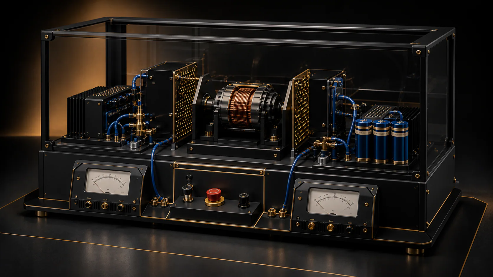
Safe Exergy Recovery Bench
- Controlled source Low-energy, current-limited supply with independent input measurement.
- Motor / coil element Known resistance and inductance with temperature monitoring.
- Controlled switching Repeatable operating point with protected switching.
- Recovery path Capture otherwise-dissipated magnetic-field energy into measured storage.
- Useful load Deliver equivalent defined work in both comparison modes.
- Independent instruments Controller telemetry cannot serve as the only proof.
03 · Primary experiment
Recovery OFF versus ON
Mode A
Recovery disabled; establish source energy and useful-output baseline.
Baseline
Mode B
Recovery enabled with equivalent source, load, target and conditions.
Comparison
Success question
Did recovery reduce net source-energy consumption for the same defined useful output?
Measure—not assume
Stop rule
If parasitic energy and added losses equal or exceed recovered energy, do not harvest.
Net recovery ≤ 0
04 · Adaptive controller
Exergy-aware routing architecture
01Sensors
02Exergy estimator
03Opportunity map
04Optimization engine
05Power router
06Storage / load
CalculateSource energy, available exergy, recoverable energy and recovered energy.
AccountConversion, switching, storage and parasitic losses.
DecideHarvest, store, transfer, convert, bypass, wait or reject.
ConstrainHard physical, electrical, thermal and safety limits override optimization.
OptimizeNet useful recovery over time—not impressive instantaneous voltage.
ReportRecovery efficiency and second-law efficiency with explicit boundaries.
05 · Digital twin first
Physics model before hardware
- Source, resistance and inductance
- Magnetic-field energy storage
- Switching waveform and recovery path
- Capacitance and storage-state change
- Conversion and thermal losses
- Useful load and parasitic power
- Exergy input, useful output, destruction and loss
06 · Illustrative ledger
Example—not measured evidence
Source input
100 J
Useful primary output
61 J
Recoverable loss
18 J
Recovered
12 J
Unrecoverable loss
21 J
Recovery consumption
3 J
Net recovery
9 J
Real ledger values must be measured or explicitly labeled simulations; values are never adjusted to make the balance favorable.
07 · Validation and anomaly protocol
Investigate extraordinary readings before interpreting them
G1Calibration verification
G2Independent input measurement
G3Independent output measurement
G4Storage-state accounting
G5Thermal and transient accounting
G6Parasitic-load accounting
G7Repeated matched trials
G8Uncertainty analysis
Check stored energy, capacitor discharge, battery-state error, inductive transients, bandwidth, RMS/phase error, instrument loading, grounding, calibration and omitted mechanical or thermal inputs. A surviving anomaly may only be labeled UNEXPLAINED / REQUIRES INDEPENDENT REPLICATION.
08 · Future channels
Only after Prototype 1
- Regenerative motors and braking
- Vibration and mechanical motion
- Waste heat and thermal gradients
- Pressure drops, airflow and fluid flow
- Solar thermal and radiative gradients
- Multi-source distributed recovery nodes
09 · Failure criteria
Reject or redesign when
- The energy balance does not close within uncertainty.
- The source of output cannot be identified.
- Measurement error explains the apparent recovery.
- Parasitic consumption eliminates net benefit.
- Cost or required gradients are impractical.
- The concept relies on perpetual motion or invalid entropy claims.
10 · Build roadmap
Advance only through evidence gates
Digital twin
Close simulated energy and storage accounting.
Gate: numerical balance within toleranceRecovery bench
Build the safe low-energy OFF/ON comparison rig.
Gate: repeatable operating conditionsIndependent validation
Repeat measurements with separate instruments.
Gate: uncertainty-bounded net recoveryAdaptive controller
Compare adaptive routing with a fixed baseline.
Gate: measurable benefit after parasiticsSecond channel
Add one physically different recovery source.
Gate: source-specific accounting closesMulti-source Core
Test exergy-aware routing across channels.
Gate: independent replication before promotionPossible novelty in adaptive control, exergy-aware source selection, dynamic impedance matching, measurement architecture and distributed routing remains a prior-art research question—not an established patentability claim.
11 · Bike-generator source audit
Claims become test questions—not evidence
| Claim area | Physical mechanism | Current support | Testable? | Use to Exergy Core |
|---|---|---|---|---|
| Bicycle generation | Mechanical work drives electromagnetic induction. | Established principle; document-specific performance unaudited. | Yes—torque, RPM, voltage, current and true power. | Controlled source and generator-efficiency baseline. |
| AC generation | Time-varying magnetic flux produces alternating EMF. | Established physics. | Yes—oscilloscope and true-power analyzer. | Waveform-aware input/output accounting. |
| Voltage transformation | Transformer exchanges voltage and current subject to losses. | Established physics; no energy multiplication. | Yes—primary and secondary real power. | Impedance and conversion-path studies. |
| Voltage multipliers | Diode-capacitor networks raise voltage while available current and energy remain source-limited. | Established circuit behavior; output-energy claims require measurement. | Yes—loaded waveform and energy tests. | Measurement-error and stored-energy case study. |
| Capacitors | Electric-field energy storage and discharge. | Established physics. | Yes—voltage, capacitance, ESR and state change. | Transient capture and storage accounting. |
| Diodes | Rectification with forward and switching losses. | Established physics. | Yes—current, voltage drop and temperature. | Recovery-path loss model. |
| Collapsing magnetic field / back EMF | Stored magnetic energy produces a transient when current changes. | Established phenomenon; recoverable fraction is system-specific. | Yes—bandwidth-qualified waveform integration. | Prototype 1 recovery hypothesis. |
| Tesla-coil concepts / 100 kV | Resonant high-voltage, typically low-current transformation. | High voltage is plausible; useful energy is not established by voltage. | Not in Prototype 1. | Safety and measurement-boundary lesson only. |
The complete source PDF itself has not been supplied to this project, so this is an audit framework—not a conclusion about the author’s full document.
12 · Five architecture studies
Different gradients require different converters
13 · Sensor and component categories
MVP instrumentation
- Current-limited low-voltage laboratory source
- Known motor, generator or inductive coil element
- Protected semiconductor switch and recovery network
- Diodes or synchronous conversion under engineering review
- Measured capacitor or low-energy storage element
- Differential voltage and current measurement
- Torque/RPM measurement where mechanical input exists
- Temperature sensors on source, coil, switch and storage
- Oscilloscope or digitizer with suitable transient bandwidth
- Independent calibrated energy meters and controlled load
14 · Planning cost
Safe bench estimate—not a quote
Source, load and inductive element
$250–$1,200
Switching and recovery hardware
$150–$800
Voltage, current and temperature sensors
$250–$1,000
Independent meters / data acquisition
$750–$4,000
Protection, enclosure and fixtures
$300–$1,500
Digital-twin and test tooling
$0–$1,000
Prototype 1 planning range
$1,700–$9,500
15 · Required success metrics
Performance without selective accounting
W available
Measured source potential
W captured
Gross recovered power
Net W
After every parasitic load
Exergy input
Relative to reference state
Exergy output
Useful-work equivalent
Exergy destroyed
Irreversibility estimate
ηII
Second-law efficiency
η conversion
Conversion efficiency
Parasitics
Sensors, switching and control
$/recovered W
Capital effectiveness
Wh/day
Energy recovered per day
Reliability
Repeatability and duty life
16 · Terminology boundary
Use only measurable control variables
Exergy
Maximum useful-work potential relative to a defined reference environment.
Engineering variable
Negentropy
Use only as a careful description of local order produced using supplied exergy while entropy is exported.
Not universal entropy destruction
Extropy / entaxy
Do not treat as interchangeable with exergy. Unless rigorous definitions and measurements are selected, keep conceptual.
Non-control variable
Gibbs / Helmholtz free energy
Legitimate thermodynamic potentials for appropriate chemical or constant-condition systems.
Not colloquial free energy
17 · Ranked first applications
Where measurable gradients may justify recovery
- Industrial inductive loads Controlled, repeatable switching losses; best MVP measurement environment.
- Regenerative robotics Known motion cycles and shared control electronics.
- HVAC and refrigeration Persistent thermal and pressure gradients; favor direct reuse before electricity conversion.
- Data centers Large steady heat rejection, but low temperature limits electric-work potential.
- Water infrastructure Pressure drops and continuous flow where added restriction is acceptable.
- Vehicles and field systems Multiple gradients but difficult duty-cycle, mass and reliability tradeoffs.
18 · Complete invention record
Decision-ready status
ProblemUseful energy is dissipated without consistent measurement of recoverable exergy or net recovery.
Scientific principleConservation of energy, exergy analysis, electromagnetic induction and entropy-generation minimization.
Energy sourceExternally supplied electrical/mechanical energy and later measured thermal, pressure, flow or radiative gradients.
Reference environmentMeasured ambient temperature, pressure and other source-specific reference conditions.
Control systemHard-limited estimator, opportunity map, optimizer and power router.
StorageMeasured low-energy capacitor or battery path selected for the test boundary.
Expected outputNo numeric claim until digital-twin and bench measurements close.
Parasitic loadSensors, processor, switching, conversion, communication and thermal management—all included.
RisksMeasurement bandwidth, phase error, stored-energy omission, switching hazards, heat and misleading interpretation.
Existing technologyRegeneration, flyback recovery, TEGs, expanders and energy-management systems require prior-art comparison.
Novelty questionsWhether exergy-aware adaptive routing, reference-state modeling and multi-channel loss mapping form a defensible combination.
Next experimentSimulate and then run the matched low-energy inductive recovery OFF/ON test.
Current status: INVENTED / UNVERIFIED · HYPOTHESIS · NOT BUILT · EXPERIMENTAL VALIDATION PENDING · INDEPENDENT REPLICATION PENDING.